1
4
submitted 5 days ago by [email protected] to c/[email protected]

I messaged the seller asking for the exact name of the connector, but they just reiterated the listing title. I need a two Metri Pack-150 connectors, but I can't find prewired ones and I'd rather not buy a 200USD kit.

2
31
submitted 1 week ago* (last edited 1 week ago) by [email protected] to c/[email protected]

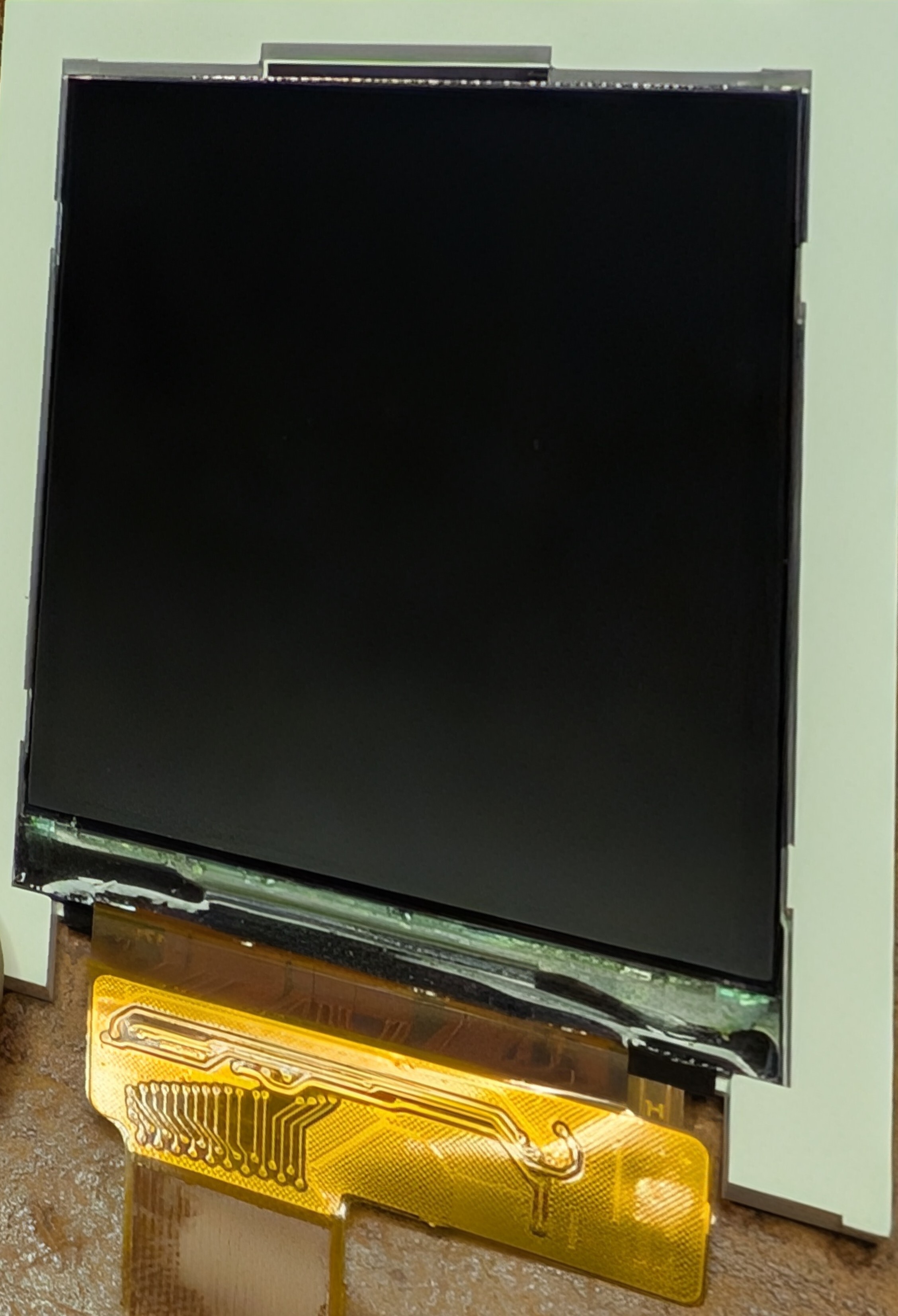
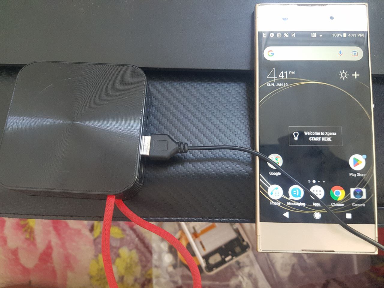
Trying to reuse this screen for a project I'm working on (yes I know I can buy another display for cheap, but I hate to waste a perfectly good display that I already have) but I am having difficulty tracking down a datasheet or even just a pin out

The text is "2.4HYDIS171+9325 24PIN", but I've tried searching it 6 ways to Sunday and nothing useful comes up.

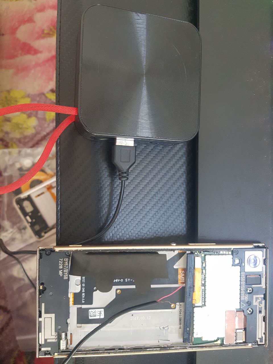
I do know that the matching pin out should have the LED anode pin on pin 1, LED K/GND on pin 2 and VCC 3.3v on pin 3. It's also a 2.4" screen and should be a resolution of 240x320

I've probably gone through a million Alibaba listings, and while some get close they just miss the mark

If anyone could help me out that'd be amazing!

Additional pics:

3
16
submitted 2 weeks ago* (last edited 2 weeks ago) by [email protected] to c/[email protected]

I have a simple circuit where 5V signal is fed into a buffer (Nexperia 74LVC1G07), then from the buffer into another device. The buffer is fed 5V by a switching DC-DC (R-78HB5.0-0.5/W). After it's been off for a while, the buffer works, the signal is recognized by the receiver. This continues for some time, minutes, to tens of minutes. Then the buffer stops working. The DC-DC still works as well as the source. If I unplug it and let it sit for an hour, it resets back to working for a while until it stops.

Context:

The setup runs on an ebike 36V battery. Theres a hub motor connected to the same battery (via power controller). The signal source is a torque sensor. The destination is a bike computer.

Any idea what could be causing this? I don't know much about electronics. I learn specific bits to do something but I'm ignorant otherwise. E.g. I know what a buffer does, I understand how it works on high level but I have no clue for example how it could be affected by the rest of the system electrically through noise, EMI, etc. My physics intuition here makes me think there must be some charge buildup happening which dissipates with time when turned off. I've no idea if this is remotely valid, or if it is how to fix it. Any ideas are appreciated!

4
28
submitted 3 weeks ago* (last edited 3 weeks ago) by [email protected] to c/[email protected]

I just found out I can buy a decent 400W solar panel in the local hardware store for around 90€ these days.

Are there people around with experience in off-grid solar? There is quite some supply in cheap MPTT charge controllers on the internet. And I can't afford a 700€ power station. But I would be able to buy a few power tool batteries or one of the lead-acid batteries people put in their caravan. Are there projects building a power station myself? Is this even worth it?

Maybe someone alredy wrote a blog post with recommendations or findings and failures along the way. Or has something similar running at home?

(Thanks to the mods for steering me towards the correct community.)

5
5
Daly BMS experience (a.aliexpress.com)
submitted 1 month ago by [email protected] to c/[email protected]

Hi all. Does anyone have experience with the BMSs from Daly? I'm looking to get a 16s BMS for a DIY li ion battery pack. I have a large box full of li ion 18650 cells and want to make an emergency battery system for home use.

That power outage in Spain motivated me to finish this project.

6
14
submitted 1 month ago* (last edited 1 month ago) by [email protected] to c/[email protected]

I'm using an Arduino and through a library working with an IC (MCP2515, a CAN controller) over SPI. The IC indicates interrupts by causing a falling edge on an interrupt pin.

Components are connected using jumper wires on a breadboard.

  • When a logic analyzer is not attached, the IRQ gets called a few hundred times. It should only be called once. I thought it must be noise on the external interrupt pin but a pull-up doesn't help. I've tried the internal pullup and an external one.
  • Trying to see if there is a ton of interrupts from the IC, or an error internal to the Arduino, I attach my logic analyzer. Now it works perfect.

Any idea what might cause such a weird issue? Looking around I haven't found anything.

EDIT: I found a Reddit post for a different circuit where a user suggested placing a small capacitor to make the edges of a signal rise slower. This has fixed my problem.

Since I've already created a post: does anyone know why I was getting an unending number of interrupts? Why would the edges of the interrupt signal changing too fast cause something like this?

7
28
submitted 1 month ago* (last edited 1 month ago) by [email protected] to c/[email protected]

It's the trace going towards the mode button, so I'm pretty sure resistance won't exactly be critical over a ~3mm gap, as long as it recognizes when the plunger button is pressed down.

8
15
submitted 1 month ago* (last edited 1 month ago) by [email protected] to c/[email protected]

Not sure if this is a dumb question but this has me quite puzzled.

The legs on TO220 packages are very small. How is it that there are e.g MOSFETS rated as being able to continuously conduct ~100A? e.g IRF1404Z

From what I understand such large currents need busbars on PCBs and these appear a lot larger than the legs on these components.

9
47
submitted 1 month ago* (last edited 1 month ago) by [email protected] to c/[email protected]

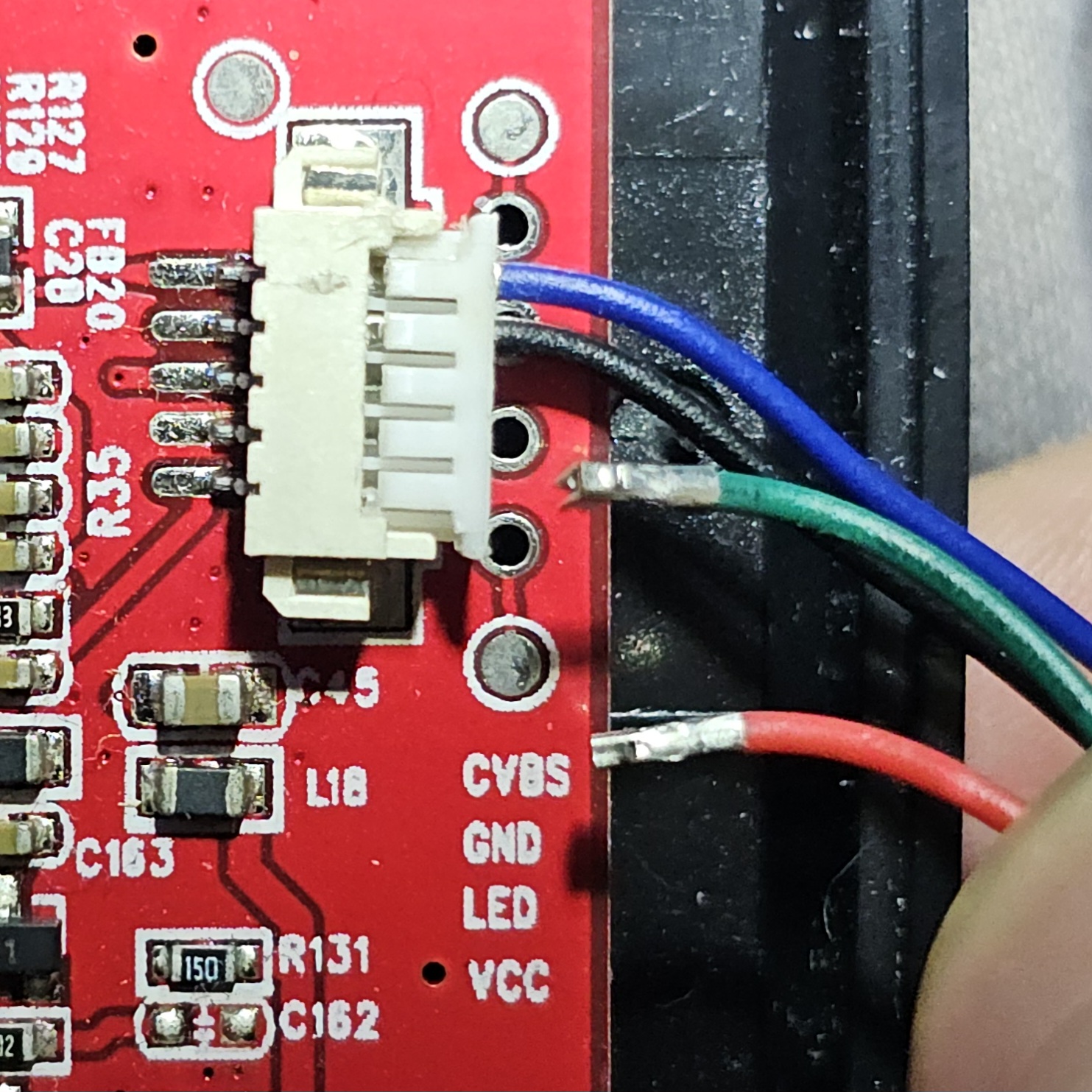
I have an inspection scope camera that I'm attempting to repair. It's one with a camera on the end of a flexible rod to see into tight spaces. The pins that lead to the camera came out of the connector. I tried looking for teardowns or even replacement parts, but found nothing.

Two pins are still inserted, but I'm not confident they are in the right places. I want to get it working without the risk of frying everything. I've done my best to find where each pin goes, but there's not enough info for me figure it out on my own. The camera rod also includes an LED for light.

Here's a photo of the connector as it is:

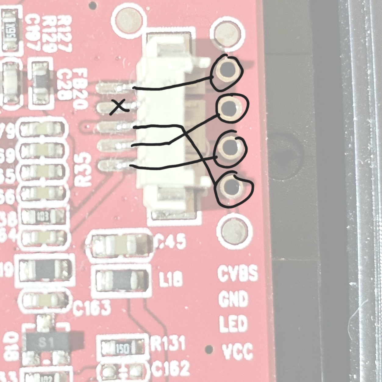
And here is the socket with it's pins labeled (the labels correspond to the testing pads and not to the socket pins):

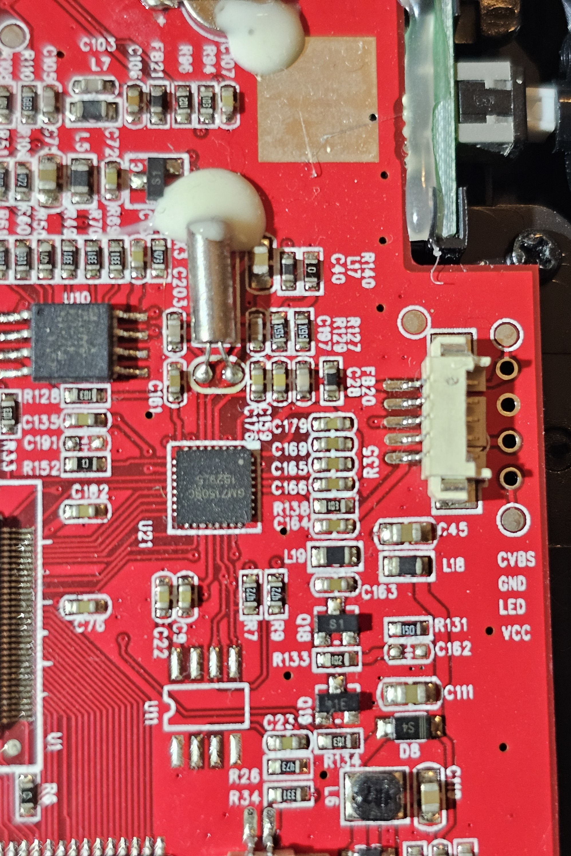
Here's a zoomed out pic if it's of any use:

I have a multimeter, so I can do any testing you can suggest. Unfortunately, I was not able to disassemble the camera to trace any wires.

10
2
submitted 1 month ago by [email protected] to c/[email protected]

cross-posted from: https://lemmy.ml/post/28250870

Hello everyone !

I'm seeding/cross-post this in 3 communities because I think I will get better answers in each respective one (Hardware, coding, electronics).

As the title say I'm want to learn to build from the ground up those cheap solar led/optic fiber lightning, here some images to get what I mean:

They come in bundles but after awhile they just die out without repair ability which kinda sucks and because they are cheap my mum keeps buying them... So, I would like to build ones I'm able to repair and customize :). However I have absolutely NO idea where to begin and what exactly I'm searching for... I'm lacking the skills and knowledge on the 3 fronts !

  • What hardware I'm looking for ?
  • What kind of electronics ?
  • What programming language to glue everything together?
  • .... ?

I'm not afraid to get my hands dirty and learn how to micro-solder, learn some coding skills to get everything neatly glued together software wise, learn the necessary hardware or other important and necessary stuff to achieve this goal ! I'm looking for every good and reliable advice to get me started !

One thing though, If i have to learn some hardware/low level coding skills I would prefer a language that would be useful for other stuff in the long run.

Thank you in advance and I'm already sorry if I'm very slow to respond, I'm not native and the flood amount of information I will probably get, will surpass my ability to respond to everyone right away.

Also every other directions are welcome, like:

  • how to repair the old ones? Do I need to flash their proprietary software/hardware?

Thank you !

11
33
submitted 2 months ago by [email protected] to c/[email protected]

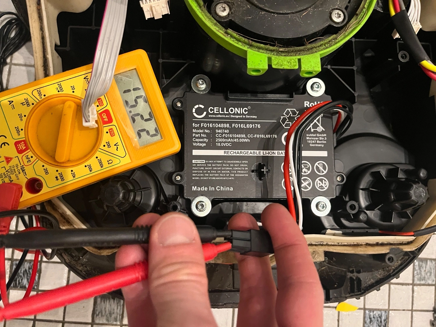
I replaced this battery last fall, but it has drained over the winter. The auto-mower dock wont charge it. Is there any feasible way to charge it safely? Or is it dead at that voltage? It’s a Bosch Indego 400. Thanks in advance.

12
15
submitted 2 months ago* (last edited 2 months ago) by [email protected] to c/[email protected]

Hi, Any1 have experience with this usb to TTL 6 pin converters? I just want to know if I have a dodgy one that I bought from Ali or normal behaviour.

Doesnt seem right. I have it plugged to a powerbank, following voltages read from pinout, without any jumper link.

5v = 5.3 Vcc = 3.9v 3.3 = 3.2v Tx RX = 3.9v

If I use jumper link from 5v to VCC, then tx RX = 5.3v, if I jumper link VCC and 3.3, RX and tx = 3.9v.

Thanks for reading

Photo of product http://0x0.st/81fc.jpg

13
9
submitted 2 months ago by [email protected] to c/[email protected]

I'm making a driver for a small 15V, hall sensored, 9-slot BLDC motor I got off of AliExpress. It has u,v,w inputs. Three hall outputs and Vcc, Gnd for them. No datasheet :)

I understand the working principle: I'll have to use the hall sensors to figure out the location of the rotor, then power the appropriate windings.

Trouble is, I don't know how the windings for the three phases are arranged within the motor. So I don't know which pin to give power to, because I don't know which windings within the motor will then be powered.

How can I figure out where the windings are for each phase?

I'm guessing I've got to manually spin the motor and do some detective work with back-emf measurements and hall sensor outputs to figure this out?

14
27
submitted 3 months ago* (last edited 3 months ago) by [email protected] to c/[email protected]

I've an UPS but it's not working fine. Disassembled it a bit and tested components that I could without unsoldering, everything seems good. Then the problem is :

  • Normally I should be able to connect the batteries and the UPS would just be in "sleep" mode, the screen would be fully light up but the UPS should be off

  • The problem here is that firstly when I plug batteries the fan turns on, it should not and only turned on when on batteries but when the UPS is on

  • The second problem is that the screen doesn't work as intended. This is a screen that has prewritten zone that just have to be lighted up (don't know the name of this kind of screens, the type like in digital clock), here only the backlight is lighted up (normally all the possible drawing are lighted up too), but quickly it begins to drop in lightness to turn black at the end (the fan continues running)

Check the batteries they are 2 x 12V at 12.6V here

Thanks for your answer

EDIT : on the photo the two blue and brown cable at right are the power plant electricity going to the UPS

15
31
submitted 3 months ago by [email protected] to c/[email protected]

So I'm not sure what the right community for this is but I'm hoping yall can help. I'm a refrigeration service tech and recently I was tasked with replacing a sensor in a room used to store ethanol drums. Due to the nature of the room every device in it had to be rated explosion proof and I couldn't use any tools that could pose any risk of ignition (no heat gun, basically nothing with an electric motor, and definitely no open flames) while working in there. Normally when I splice wires I use heatshrink to cover the splice simply because it looks far more professional than electrical tape and it holds up better over time. However in this case I could not figure out any way of shrinking said heatshrink without posing a potential ignition hazard so I was stuck just wrapping the splice in tape. We do a lot of work for this company so I'm hoping to find a better solution for the next time I am in a similar situation.

So do any of you know any way to shrink heatshrink without posing an ignition hazard or am I stuck just using tape in those situations?

16
21
submitted 3 months ago by [email protected] to c/[email protected]

Hi all! I'm a firmware developer with little knowledge in analog electronics.. I deal with firmware for IOT projects all the time.

I had to make a breakout board with an off the shelf RF module with self contained PCB antenna. Now I'm intrigued in the hardware side. I'm inclined to design them from scratch myself. (Obviously ignoring the EMI and FCC certifications for the time being).

What concepts should I be familiar with to achieve this? Starting on I figured to brush up on circuit theory and signals. Where do I go from here? What materials would you recommend? Hopefully I don't need to get into hardcore RF theory to design these PCBs (I know kicad already has these premade antenna blocks).

Thank you.

17
16
submitted 3 months ago by [email protected] to c/[email protected]

I'd like to build a small light that i can use to cast a shadow to a wall.

It needs a single led that's really small and bright and that can be recharged. Also I want to put it in a special casing.

However I don't really know how to build one myself. So I had the I bright idea to take apart a flashlight that is rechargeable, but I'm not sure which one can be dismantled.

Do you have any idea what flashlight I could use or what parts I would need?

18
31
submitted 3 months ago by [email protected] to c/[email protected]

Why do you like it? Why did you choose it? Would you recommend it?

19
16
submitted 4 months ago* (last edited 3 months ago) by [email protected] to c/[email protected]

I'm looking for a recommendation on a high quality 2 or 3 meter USB-C /Thunderbolt cable used for data transfer and charging.

After yet another replacement Anker cable usb-c cable I’d really like to get cables that can last a few hundred cycles and I need a recommendation.

Are there any companies that make higher durability cables?

--Edit-- So far recommendations I have gotten are

  • Samsung
  • LCom
  • cable matters
  • Braided jackets
  • Power delivery of 25w or greater
  • Use magnetic disconnects
20
24
submitted 4 months ago* (last edited 4 months ago) by [email protected] to c/[email protected]

I have an UPS with two 12v 7ah lead batteries. If I want to change the batteries I would typically go with lead batteries but here's my question, can I use some portable mobile power banks to use it?

Because I have a 20000mah "INUI" lithium power bank that is rated for 12v at 1.5A, is it a good practice to buy several of these (since they are about 20 bucks) disassemble them and use them as ups batteries?

EDIT : clarifications

21
36
submitted 4 months ago by [email protected] to c/[email protected]

So, i'm thinking of a story and i need some tech info.

How risky is to de-solder an usb plug if the flash-drive contains important files? It would be relatively safe for someone capable, or the heat is way too risky for the chip/content?

Also there's any (MacGyver like) way to quickly access the file or reconnect the plug without a solder while only having access to office supplies?

22
11
submitted 4 months ago by [email protected] to c/[email protected]

I have a pet project I've been working on to modernize an electric organ console, and one of the final things needed are toggle switches. On a modern organ these are able to be manually toggled, or they can be flipped up/down programmatically using electromagnets (video). The ones purpose built for this are obscenely expensive but I can't find anything even remotely similar. Am I crazy for thinking this kind of switch are used in more things than just organs?

23
24
submitted 4 months ago* (last edited 4 months ago) by [email protected] to c/[email protected]

Hi all,

Do you have some recommendations for a soldering station that would meet my needs?

I've been into hobby electronics for a few years, doing mostly analog audio projects but recently got into repairing and repurposing broken electronics (Bluetooth earbuds, speakers, USB cables and such).

I've been using a cheap Parkside(LIDL)-rebranded "generic Chinese product" (I came across the exact same model on AliExpress, in different colors); which has served me well until now but has a few flaws that I can't be bothered with anymore. Mainly: -it takes ages to get hot. -the cable going from the station to the iron is super thick and stiff, which is annoying as hell...

I would like it to be the least expensive possible, while being good enough I'd be happy with it for the foreseeable future.

I have been looking at these:

Old tech, cheap tips (<1€)

Newer tech, "expensive" tips (8-10€)

And wondering how these "newer" types of iron compare to stations, what are the main drawbacks?

Thanks a lot in advance for any input, Please be gentle if you think I'm an idiot :)

Edit: changed the "Smolderin" in title to "soldering"

24
7
submitted 4 months ago by [email protected] to c/[email protected]

I've got a used riello ups recently and it was not working since the beginning. The UPS was switching to batteries most of the time, but sometimes it just don't switch to batteries and makes a continuous beep (riello manual tells that it's a UPS fault anything except an overload).

I left it 2 weeks without using it. But know it won't start at all. Don't have the materials to test components for now but what are your ideas? (Even when plugged in the wall it wouldn't start)

Maybe batteries or faulty ups

Thx

25
5
safe? (lemmy.ca)
submitted 4 months ago by [email protected] to c/[email protected]

view more: next ›

Ask Electronics

3665 readers
1 users here now

For questions about component-level electronic circuits, tools and equipment.

Rules

1: Be nice.

2: Be on-topic (eg: Electronic, not electrical).

3: No commercial stuff, buying, selling or valuations.

4: Be safe.


founded 2 years ago
MODERATORS